THE WATKINS COPICAT SUPER IC
The Super IC began life as an 'Infinite Reel' and 'Sound on Sound' echo unit. Charlie Watkins was always an innovator
and thought that the endless tape loop would make it unnecessary to frequently replace tape loops.
Should anyone have a full-on image of an original Super IC complete with its tape spool and ABS case, and who might be happy to see it displayed here, please get in touch. Your name will be added to its credits.
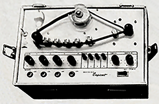
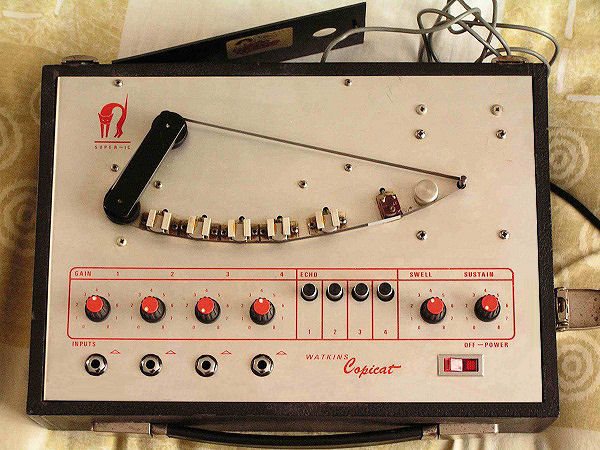
Straight away you will notice the tape system is different to that of any other Copicat. This is an endless cassette probably made by Sony, there is no jockey arm to tension the tape, just a single roller where it normally would have been. There is a small felt pad on a spring steel mounting attached to the face plate. This applies a little pressure to the tape holding it against the combo erase / record head, whilst at the drive spindle there is now a pinch roller, creating extra grip against the motor spindle, which together keeps the tape taught against the heads. To the left of the picture is a toggle switch. This is the Sound On Sound switch, which actually switches off the erase head, allowing the sound to build up on the tape eventually to an unbearable noise. I think the general idea was possibly to build a loop of a number of bars within a single revolution of the tape which you could jam along to using another amplifier. Providing the swell was set at zero (no signal feed back) to some extent this would work, but the machine wasn't very successful, and many were modified back to a normal Copicat without the S O S facility. The tape mechanism also tended to tangle and give problems, so that too was converted to the usual jockey arm tape loop system.
To view an advertisement and a review click here.
Here is a machine that has been reverted from a S O S Copicat to the standard Super IC with jockey arm and normal tape loop.
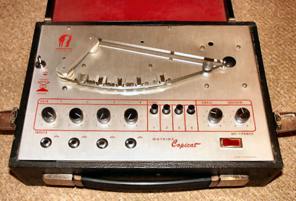
Due to problems with the cartridge tape mechanism and the tape tangling, these models were reverted to the normal Copicat jockey arm tensioning device together with a standard 22.5-inch tape loop. I now know from a former employee, that this was a factory modification to the previous machine where they have dropped the cassette idea but continued to use the stocks of previously punched faceplates.
This one you can see has retained the Sound On Sound Switch on the left, but no longer has the tape cassette or the rubber pinch roller. There is a hole where the cassette spool was fitted and a blanking grommet where the pinch roller would have been.
For a while retaining the sound on sound facility, which with the shorter tape loop was pretty much useless. The S-O-S facility was soon dropped, by removing the switch and plugging the hole with a grommet.
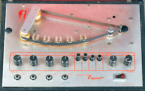
Similar to unit above but without the 'Sound on Sound' switch.
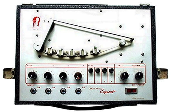
Here is a later version with a newly manufactured faceplate without any evidence of the previous holes or the S-O-S facility.
Worth a mention, as you may have noticed that this, and all the above versions, have five heads, the first left being a dual or combination head containing the erase and record heads within a single housing. The bias signal is fed to the erase section only, the recording bias being induced from the erase section by the proximity of the erase and record coils. The other four heads are all playback heads, selected by any or all of the four pushbutton switches. They can be selected singly or in multiple combinations.
For the technically minded person, the versions with the S-0-S facility, the bias signal to the erase section of the combination head is switched off, but is then diverted to the record section via a resistor to be able to record and build sound on sound without erasing the tape, which on a small loop just ends up as a total mess!
The super IC has a lead storage compartment in
the rear closed in by a thin plastic door.
'Super IC' screen printed on the
face plate to the left of the jockey arm.
This one courtesy of Bob Rumble is a later 6 head version. Left to right are, 1, Record head, 2,3,4,5 Playback heads, which are selected by the Echo Buttons, and 6, often thought to have its cover missing, is the erase head. The machine has a 4 input mixer with individual gain controls 1,2,3&4 for instruments and or microphones as required. Fitted in the rear compartment is a 3 contact socket called a break-in socket, or effects send and return, for an external processor. This facility works in conjunction with channel 4 only. To the right is the "Swell" or echo volume in relation to the dry or real-time level. The "Sustain" is a feedback control which feeds some of the echo effect signal back to the record amp to be re-recorded to give multiple echoes according to how high it is set. Saturation point is when the level of swell become too much and the machine oscillates and produces the familiar spacey Telstar sound.
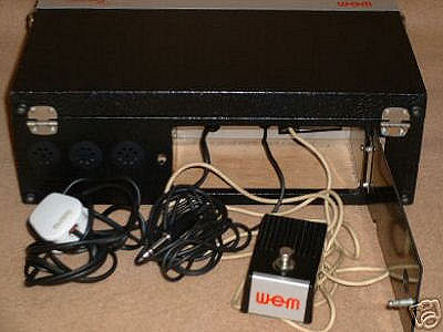
Super IC rear storage compartment showing inside jack sockets for footswitch and break-in point.
Here we can see good front and rear views of the Super IC heads.
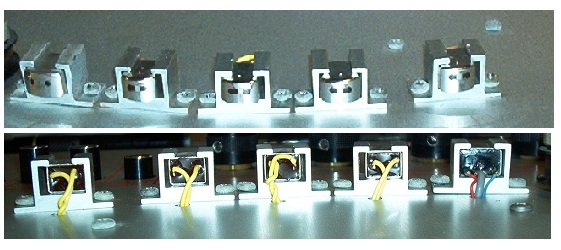
The heads are half track mono cassette player heads with an inductance of about 150 mH. The top picture shows the combination erase record head on the left whilst the lower picture shows it on the right, as you can see it has 4 terminals whilst the others have only 2.
Below shows an example of a badly worn head.
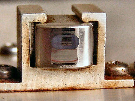
The face of this head is beyond repair and in dire need of replacement. You can see the two poles of the central pickup area and the gap between them, which due to wear is much wider than the few microns that it should be. The brackets being wider than the heads within them makes it difficult to set the heads parallel to the tape path, as it shows in this image where the wear is towards the left side of the head face rather than central to it. You can also see that the wear is heavier at the bottom of the head than at the top. The uneven wear indicates that both the Zenith (angle fore and aft) and Azimuth (left/right perpendicular adjustment of the head) is way out of spec. These extruded aluminium brackets have no adjustment facilities and were not made specifically for the job.
The inside base/floor of the bracket is rarely flat, and can be improved with a file. The head needs to be central within the bracket and parallel to the sides. I supply a U-shaped tool to help centralise the heads I supply as replacements. I have to say that this and the IC400 playback heads' clamp brackets are the worst bracket arrangements that w-e-m ever came up with.
Heads in this state will rapidly wear the tape out, and the reproduction will be poor with loss of highs, and excessive noise levels. You can also see ferric oxide shredded from the tape all around the bracket and mounting screws.
Here is a jpeg copy of the Super IC instruction sheet, sorry the quality isn't too good, there is a better pdf version as well.
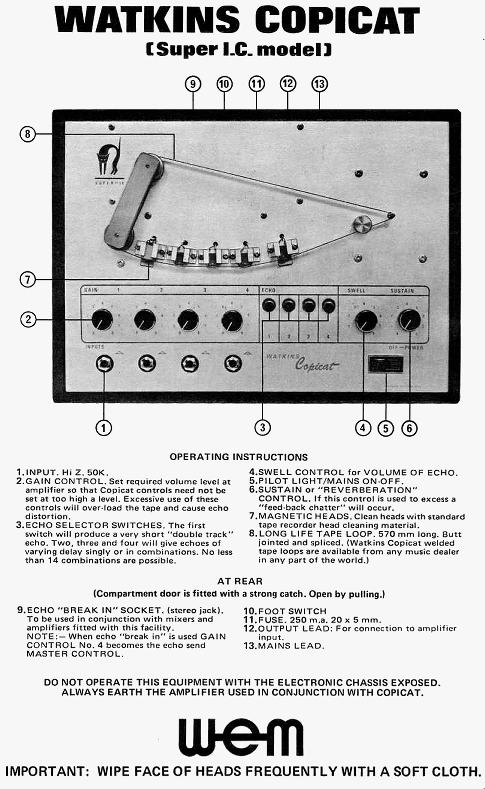
Click the link below for a PDF version of the Super IC
instructions. You will need Acrobat Reader to view this file,
download for
free from Adobe.